Telescoping GPU Sag Brace with Cable Comb
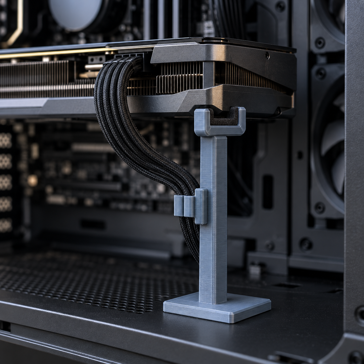
A height-adjustable brace that props up a heavy graphics card from underneath and clips its power cable into a comb so nothing dangles.
Telescoping GPU Sag Brace with Cable Comb
A height-adjustable brace that props up a heavy graphics card from underneath and clips its power cable into a comb so nothing dangles.
Date: 2026-09-23 Category: Desk and Tech Modeling difficulty: Advanced Estimated print: ~7 h total · ~115 g PETG + TPU (estimate) Suggested price: $18–$26 printed · $5 digital file (estimate) Status: Concept
Description
Big graphics cards sag. A four-slot cooler weighs enough to bow the PCIe slot over months of use, and most fixes are either a $30 metal jack stand that only holds one height or a Command strip that eventually gives out. This brace is a magnetic base plate, a telescoping post, and a cradle that locks at whichever height lines up with the card's underside.
The post has eleven pin holes on 5 mm centers, so it adjusts for cases with different floor-to-GPU distances instead of shipping as one fixed size. A padded trough on top spreads the load along the card's edge rather than poking a single point into the shroud, and a snap-on comb further up the post keeps the 12VHPWR or 8-pin cable from flopping across the case interior.
Four disc magnets on the base hold it to a steel case floor without screws, so it goes in and comes back out in seconds if the build changes.
Why it sells
GPU sag brackets are a recognized category on Etsy, not a novelty — dozens of active listings sell adjustable anti-sag supports, from plain jack stands to themed ones with painted figures on top, several with five-star review histories (Etsy: gpu_support market, adjustable bracket listing, 50–65 mm bracket listing). BGR's 2026 roundup of desk gadgets worth 3D printing instead of buying names GPU supports specifically, alongside cable mounts and fan guards, as items PC builders print rather than order (BGR: desk gadgets to 3D print).
What's missing from the listings we found: none of them also manage the power cable. Builders end up printing a bracket and buying a separate cable comb. This design folds both into one post.
Who buys it
PC builders and upgraders, mostly people who just installed a longer or heavier card than their case was designed around. It sells around GPU launch windows and during PC-building season (back-to-school, Black Friday builds), and it lives on the same shelf as case fans and RGB strips — Etsy, a PC-parts subreddit giveaway, or a local PC-building meetup table.
Design overview
- Telescoping post with 11 pin-lock height positions, 5 mm apart, covering roughly 45–95 mm of case floor-to-GPU clearance
- TPU friction pad in the cradle so the card's shroud doesn't rest on bare plastic
- Four-magnet base for tool-free removal from a steel case floor
- Snap-on cable comb that clips anywhere along the post, independent of the cradle height
- All structural parts in PETG for creep resistance under sustained load — PLA can slowly deform under a card's weight over months
- Two locking pins included so a dropped or lost pin doesn't strand the brace mid-build
Dimensions
| Measurement | Value (mm) | Notes |
|---|---|---|
| Base plate footprint (X × Y) | 70 × 60 | |
| Base plate thickness | 16 | |
| Riser post height | 70 | |
| Riser post cross-section | 27.8 × 27.8 | hollow, 3 mm wall |
| Cradle footprint (X × Y) | 65 × 34 | |
| Cradle height | 18 | |
| Assembled height, max extension | 95 | pin at topmost hole |
| Assembled height, min extension | ~45 | pin at lowest hole |
Parts list
| Part | Qty | Material | Size X×Y×Z (mm) | Print orientation | Supports |
|---|---|---|---|---|---|
| Base plate | 1 | PETG | 70 × 60 × 16 | flat, bottom down | none |
| Riser tube | 1 | PETG | 27.8 × 27.8 × 70 | vertical, bottom down | none |
| Locking pin | 2 | PETG | 8 × 8 × 22 | vertical, head down | none |
| GPU cradle | 1 | PETG | 65 × 34 × 18 | flat, socket face down | none |
| Friction pad | 1 | TPU | 55 × 18 × 2 | flat | none |
| Cable comb | 1 | PETG | 40 × 15 × 12 | flat, back face down | none |
Hardware and non-printed parts
- 6 mm diameter × 3 mm thick N35 disc magnet ×4 — glued into the base plate's underside pockets, flush with the bottom face
Fits and tolerances
| Parts | Fit type | Clearance per side |
|---|---|---|
| Base plate socket ↔ riser tube | Press (permanent) | 0.1 mm |
| Riser tube ↔ GPU cradle socket | Sliding (adjustable) | 0.2 mm |
| Riser tube pin hole ↔ locking pin | Sliding, snug | 0.15 mm |
| GPU cradle trough ↔ friction pad | Press | 0.1 mm |
| Riser tube ↔ cable comb prongs | Snap | 0.15 mm |
Modeling guide
Global origin: center of the base plate's bottom face. +X right, +Y toward the back of the case, +Z up.
Base plate
- Sketch a 70 × 60 mm rectangle on XY at z=0, centered on the origin, corner radius 4 mm.
- Extrude 16 mm in +Z.
- On the top face, sketch a 28 × 28 mm square centered at (0,0) and pocket-cut it 10 mm deep.
- On the bottom face, sketch four 10 mm diameter circles at (±25, ±20) and pocket-cut each 3 mm deep for the magnets.
- Chamfer the top outer edge 1 mm × 45°.
Riser tube
- Sketch a 27.8 × 27.8 mm square (corner radius 1 mm) on XY at z=0, centered on its own local origin at the bottom end.
- Extrude 70 mm in +Z.
- Shell inward 3 mm, leaving the top and bottom faces open.
- On the front wall, sketch 11 circles, 3.3 mm diameter, centered on the face width, at Z = 15 through 65 mm in 5 mm steps.
- Cut each hole through both the front and back walls.
Locking pin
- Sketch a 3 mm diameter circle at z=0, extrude 20 mm (shaft).
- On top, sketch an 8 mm diameter circle and extrude 2 mm (head disc).
GPU cradle
- Sketch a 65 × 34 mm rectangle (corner radius 3 mm) on XY at z=0, centered on its own local origin at the bottom face. Extrude 18 mm in +Z.
- On the bottom face, sketch a 28.2 × 28.2 mm square centered at (0,0) and pocket-cut 10 mm deep.
- On the top face, sketch a 55 × 18.2 mm slot (4 mm corner radius) centered at (0,0) and pocket-cut 8 mm deep.
- On the socket side wall, sketch a 3.3 mm diameter circle centered at Z=5 mm (measured from the part's own bottom face) and cut it through both socket walls.
Friction pad
- Sketch a 55 × 18 mm rectangle (corner radius 2 mm) and extrude 2 mm.
Cable comb
- Sketch a 40 × 15 mm rectangle on XY at z=0, centered on X, from Y=0 to Y=15. Extrude 12 mm in +Z.
- On the top face, sketch 6 rectangles, each 3 × 15 mm, spaced 3 mm apart, centered as a group on X=0, and pocket-cut each 6 mm deep.
- On the back face, sketch two 1.5 × 8 mm rectangles centered at X=±14 mm, from Z=0 to Z=10 mm, and extrude each 6 mm in −Y to form the snap prongs, leaving a 28.1 mm inner gap between them.
Print settings
| Setting | Value |
|---|---|
| Material | PETG (structural parts), TPU (friction pad) |
| Nozzle | 0.4 mm |
| Layer height | 0.2 mm |
| Walls / perimeters | 4 |
| Infill | 25% grid |
| Supports | none |
| Brim / adhesion | 5 mm brim on the riser tube only — it's tall and thin on a small footprint |
| Notes | Swap to TPU filament for the friction pad only; everything else stays PETG |
Assembly
- Press the riser tube into the base plate's socket until it seats flush. Add a drop of plastic-safe adhesive if it feels loose.
- Glue the four magnets into the base plate's underside pockets, flush with the surface.
- Press the TPU friction pad into the cradle's trough.
- Slide the cradle onto the riser tube, find the pin hole that puts the trough level with the GPU's underside, and insert a locking pin.
- Snap the cable comb onto the riser tube wherever it's convenient and route the power cable through its slots.
- Set the base plate on the case floor under the card. The magnets hold it to a steel floor; slide the assembly until the cradle sits under the card's far edge.
Variants and upsells
- A shorter riser (parametric
riser_heightdown to 50 mm) for small-form-factor cases - A wider trough (
trough_lengthup to 80 mm) for full-length triple-fan cards - A no-magnet variant with a wider base footprint for glass or non-ferrous case floors
- Bundle: brace + comb + a matching drive-bay blanking panel as a "case cleanup" three-pack
Selling and distribution
List on Etsy and MakerWorld, where the anti-sag bracket category already has buyer traffic — new listings there compete on adjustability and the cable-comb integration rather than starting from zero. Price the printed unit around $18–$26 based on ~115 g of filament and 7 hours of machine time at typical Etsy PC-accessory margins; sell the STL/3MF bundle separately for around $5 under a commercial-use license, since builders searching "GPU support bracket" skew toward buying the physical part rather than printing their own. Keywords: gpu support bracket, graphics card sag fix, gpu anti sag, cable comb, pc case accessory, gpu brace adjustable, pc builder gift, graphics card holder.
Risks and IP notes
- The riser tube is a tall, thin print on a small footprint and can tip mid-print without a brim — brim is specified, don't skip it.
- The category is crowded on Etsy; differentiate on the cable comb and the pin-adjustable height rather than price.
- PLA creeps under sustained load — this design specifies PETG for exactly that reason; don't substitute PLA for the structural parts.
- No sports-team, brand, or character marks are used anywhere in the design or listing photos.
Resource links
- BGR: 10 desk gadgets to 3D print instead of buying — names GPU supports as a category PC builders print rather than buy
- Etsy: gpu_support market — shows the number of active sellers in this category
- Etsy: GPU Support Bracket 3MF File, adjustable — a comparable adjustable digital-file listing
- Etsy: GPU Support Bracket 50–65mm STL File — comparable size range for GPU brackets
- Etsy: GPU Support Anti-sag 3D Printed — a physical (not digital-file) listing in the same category
More from 3D Print Designs