Twelve-Cam Travelling Wave: Hand-Crank Desk Sculpture
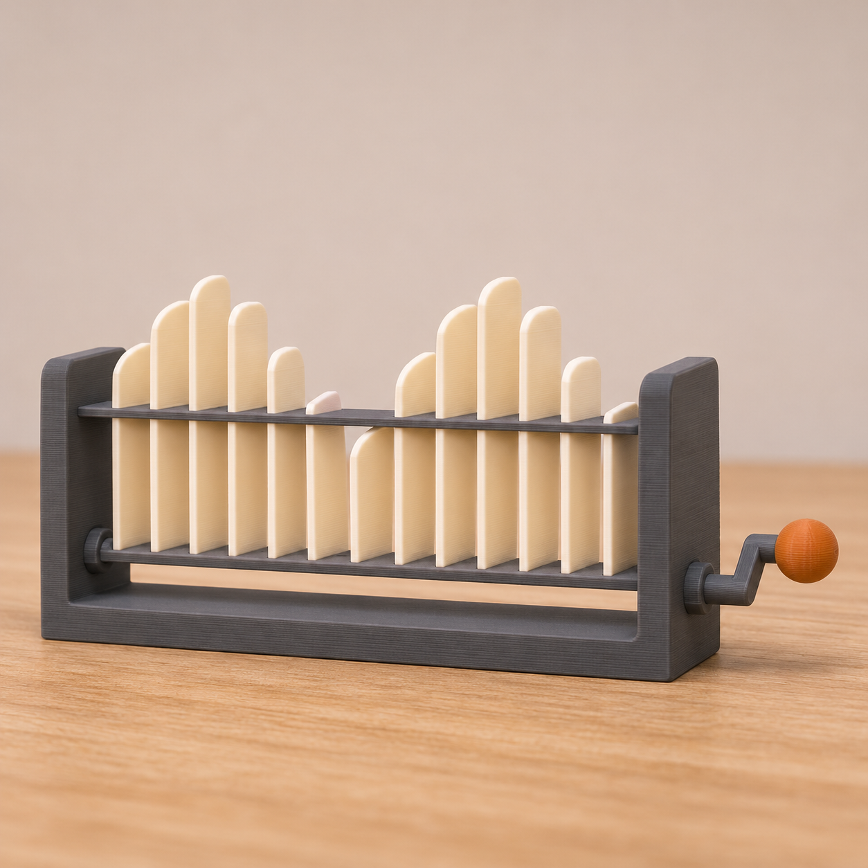
A hand-cranked row of twelve fins that rise and fall as a smooth double wave, built from one cam part printed twelve times and a hex shaft.
Twelve-Cam Travelling Wave: Hand-Crank Desk Sculpture
A hand-cranked row of twelve fins that rise and fall as a smooth double wave, built from one cam part printed twelve times and a hex shaft.
Date: 2026-11-12 Category: Art and Decor Modeling difficulty: Advanced Estimated print: ~21 h total · ~255 g PLA (estimate) Suggested price: $65–$130 printed · $12 digital file (estimate) Status: Concept
Description
Turn the crank and a wave runs along a row of twelve white fins. Two crests travel at once, because the cams are staggered 60° apart and the pattern repeats after six. The fins slide in two guide plates, stand on eccentric-disc cams, and drop back by gravity, so there are no springs, rods or bought parts at all.
Wave machines are a known kinetic-art form, so this is not new as a category. What is different here is the construction. Every cam is the same printed part. Each has a 10.3 mm hex bore and an eccentric disc, and you pick the phase by choosing which of the six hex positions it slides on. A flat fin resting on an eccentric circle moves in a true sine, with no cam profile to calculate. The result is a desk piece that is quiet, hypnotic, and cheap in filament terms for its size.
The frame is charcoal, the fins warm white, and the crank knob a single accent colour.
Why it sells
This is an art idea, chosen on taste, not on sales numbers. The form has an audience: Printables hosts a "Kinetic Art Wave Machine" driven by a camshaft (Printables 734776), a "Horseshoe Waves Kinetic Sculpture" exists in 8 and 16 follower versions (Thangs), and there are crank-automaton kits and build guides (ATOMM Kinetic Wave Machine, Instructables MicroWave). Those use a helical camshaft with each cam offset by a fixed angle, which is the principle used here. The ATOMM page says each of its cams is calculated so the wave is a true sine. The gap: most designs need a keyed or glued shaft, or bought rod and bearings. A hex shaft with identical cams needs none of that, and the 60° indexing makes assembly a counting exercise.
Who buys it
Desk-sculpture and kinetic-art fans, engineers, teachers explaining waves, and people who give gifts that "do something". They shop on Etsy and at design markets, and the file suits Printables or MakerWorld. It is also a good display piece for a print shop's stand because it moves.
Design overview
- A U-shaped frame: a 192 × 64 × 6 mm base with two 6 mm end walls, 80 mm tall.
- Twelve fins, each 5 × 14 × 70 mm, riding in two 6 mm guide plates that drop onto 45° ledges in the end walls.
- Twelve identical cams: a disc 26 mm across, 8 mm thick, offset 6 mm from the shaft axis by a hex bore, with a 6 mm hub. 12 mm of travel per fin.
- A hex shaft, 10 mm across flats, 204 mm long, turned by a printed crank with an 18 mm arm and a 16 mm knob.
- Cam k sits rotated k × 60°, which gives six phases and two full waves across the row.
- Sets it apart: one cam part, twelve copies, phase set by which hex position it slides on, with a true-sine motion from an eccentric circle. No bought parts.
Dimensions
| Measurement | Value (mm) | Notes |
|---|---|---|
| Overall width (X) | 216.4 | frame 192; shaft end cap and crank add 24.4 |
| Overall depth (Y) | 64 | frame width |
| Overall height (Z) | 117 | at the highest fin position; 105 at the lowest |
| Wall thickness | 6 | frame walls, guide plates |
| Shaft axis height | 28 | above the frame bottom, on the centreline y = 32 |
| Cam eccentricity | 6 | fin stroke is 12 |
| Cam disc diameter | 26 | |
| Cam pitch along shaft | 14 | disc 8 + hub 6 |
| Fin size | 5 × 14 × 70 | X × Y × Z |
| Guide plate slot | 5.4 × 14.4 | 0.2 mm per side around the fin |
| Frame inner length | 180 | between end walls |
Parts list
| Part | Qty | Material | Size X×Y×Z (mm) | Print orientation | Supports |
|---|---|---|---|---|---|
| Frame | 1 | PLA | 192×64×80 | base down | none (ledges are 45° triangles) |
| Guide plate | 2 | PLA | 179.6×28×6 | flat | none |
| Fin | 12 | PLA | 70×14×5 | lying on the 14 mm face | none |
| Cam | 12 | PLA | 26×26×14 | disc face down, hub up | none |
| Hex shaft | 1 | PLA | 204×11.6×10 | flat on a hex flat | none |
| Crank | 1 | PLA | 16×36×20 | hub axis horizontal, knob side down | none |
| End cap | 1 | PLA | 20×20×8 | flat face down | none |
Hardware and non-printed parts
Cyanoacrylate or PLA-safe glue for the crank and end cap (two joints). Optional: a drop of candle wax or dry PTFE lubricant on the shaft holes and fin slots. No bought mechanical parts.
Fits and tolerances
| Mating parts | Fit | Clearance |
|---|---|---|
| Cam hex bore to shaft | sliding (cams must slip on, then stay put by hex friction) | 0.15 mm per side |
| Shaft to frame hole | rotating, loose | 0.43 mm per side (hole 12.4 round vs 11.55 across corners; spares for print error) |
| Fin to guide slot | sliding | 0.2 mm per side |
| Guide plate to frame inner length | drop-in | 0.2 mm per side in X |
| Crank and end cap to shaft | glued press fit | 0.15 mm per side; 0.6 mm of glue gap at the socket end |
Modeling guide
Origin at the frame's bottom-left-front corner. +X along the shaft, +Y across the frame, +Z up.
- Frame base: rectangle 192 × 64, extrude 6.
- End walls: rectangles 6 × 64 at x = 0 and x = 186, extrude up to z = 80.
- Shaft holes: Ø 12.4 through both walls, axis at y = 32, z = 28.
- Ledges: on the inner face of each wall (x = 6 to 10 and x = 182 to 186), a right triangle in the XZ plane, 4 wide by 4 tall, flat top at z = 52 and again at z = 72, 28 wide in Y centred on y = 32. The flat side faces up, the slope faces down toward the wall.
- Guide plate: rectangle 179.6 × 28, extrude 6. Cut 12 rectangular slots 5.4 (X) × 14.4 (Y), centred on y = 14, at plate-local x = 12.8 + 14 i for i = 0 to 11. The plate sits at x = 6.2, one at z = 52 and one at z = 72.
- Cam: on the XY plane draw a hexagon, 10.3 across flats, centred on the origin with a corner at +Y. Extrude 14 along Z. Union a Ø 14 hub (6 high). Union a disc: Ø 26 × 8, centre offset 6 toward +Y, on the opposite end. Cut the hex bore through everything. Cut a Ø 2 × 1 deep dimple on the hub end face, at radius 6.5 toward +Y.
- Fin: rectangle 5 × 14 on the YZ face, extrude to 70 tall. Fillet the two top edges R 2.5 across the 5 mm width.
- Shaft: hexagon, 10 across flats, extrude 204.
- Crank: hub Ø 20 × 8, socket hex 10.3 across flats and 6.4 deep. Add an arm 18 long (centre to knob centre), 10 wide, 6 thick, flush with the hub's outer face. Add a knob Ø 16 × 12 centred at the arm's end, spanning 4 to 16 mm of the crank's X length. Fillet the knob R 2.
- End cap: Ø 20 × 8 with a 6.4 deep hex socket of 10.3 across flats.
Print settings
| Setting | Value |
|---|---|
| Material | PLA |
| Nozzle | 0.4 mm |
| Layer height | 0.2 mm (0.16 mm for cams) |
| Walls / perimeters | 4 (cams and fins), 3 (frame) |
| Infill | 20% gyroid (frame and plates), 100% (shaft, cams) |
| Supports | none |
| Brim / adhesion | brim 5 mm on the frame and plates |
| Notes | Print one test cam first and check it slides on the shaft. Scale the hex bore ±0.05 mm if needed. |
Assembly
- Glue the end cap on one end of the shaft (shaft sticks out 6 mm). Let it cure.
- Set the frame on the table. Slide the shaft through the left wall hole, drop cam 1 in, and push the shaft through its bore. Keep the dimple at 12 o'clock.
- Continue with cams 2 to 12, each rotated a further 60° clockwise: dimple at 2, 4, 6, 8 and 10 o'clock, then 12 again at cam 7 and so on.
- Push the shaft out of the right wall hole and glue the crank on, so the hub sits flush with the wall.
- Drop the two guide plates onto their ledges.
- Drop the twelve fins in through the slots, tall end up, and rest them on the cams. Turn the crank and check that each fin lifts freely.
Variants and upsells
- A 16-cam long version with 45° phases (8 phases, 2 waves) and a 24-cam version.
- Colour sets: fin gradient from deep blue to white.
- A single-wave small desk version, six cams, 120 mm wide.
- A motor-driven version (add a 6 mm gear motor, separate listing).
- A "wave and crest" bundle with the Lunar Tide Ring.
Selling and distribution
Sell finished sculptures on Etsy and at markets, because motion sells in photos and video. Sell the file on MakerWorld and Printables with a commercial-use tier. Price from filament (~$5), 21 h of machine time, assembly work, and margin: $65 to $130 (estimate). Licensing: CC BY-NC for free personal use, a paid licence for print sales. Keywords: kinetic sculpture, wave machine, desk toy, hand crank, cam automaton, kinetic art, wave sculpture, desk decor, 3D printed mechanism, fidget art.
Risks and IP notes
- Category saturation: wave machines already exist on Printables and Thangs. Mitigation: lead with the one-part cam and the no-hardware build.
- Fit sensitivity: a loose hex bore lets cams slip. Mitigation: 0.15 mm clearance, a test cam, and a drop of glue per cam if needed.
- Long print: 21 h across several sessions. Mitigation: print cams and fins in two batches.
- Ledge strength: 4 mm triangles carry only plate weight. Mitigation: print the frame with walls along the load path, 4 walls.
- IP: nothing branded; check any single named design before reusing its look.
Resource links
- Printables: Kinetic Art Wave Machine — a printable camshaft wave machine for comparison
- Thangs: Horseshoe Waves Kinetic Sculpture — 8 and 16 follower printed versions
- ATOMM Kinetic Wave Machine — crank-driven kit with a helical camshaft and calculated sine cams
- Instructables: MicroWave — a 24-segment build with cams staggered at a fixed angle
- Textile Academy: Sculpture 3, Amphitrite — a wave sculpture with dowel followers, for the art side
More from 3D Print Designs